Visualization Toggles in the Tool Center Point (TCP)
What You See
Four toggle switches control different visualization options: Show Tool, Show TCP, Cut on Fly, and Show Mounting Plane.
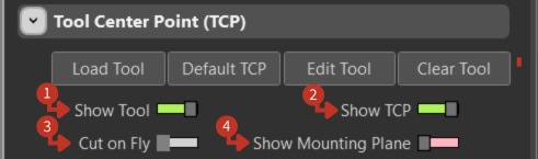
TCP visualization controls for customizing tool and workspace display
What It Means
Each toggle switch corresponds to a different feature that can be turned on or off, providing the user with customizable control over how they interact with and visualize the robot's programming setup.
Show Tool
This switch controls the visibility of the tool within the software environment. When activated, it displays a visual representation of the tool that is currently in use, providing clarity on the tool's shape, size, and positioning.
Show TCP
This toggle enables the visualization of the Tool Center Point. Turning this feature on allows the user to see the precise point on the tool that is considered the reference for all movements and operations, which is essential for accurate task execution.
Cut on Fly
The activation of this switch would allow the robot to perform tasks such as cutting while moving, without the need to stop. This could be critical for dynamic operations where efficiency and continuous motion are required.
Show Mounting Plane
This switch likely toggles the display of the plane on which the tool is mounted. With this feature enabled, users can visualize the orientation and alignment of the tool relative to the robot arm, which is crucial for tasks that depend on the tool's angle and position.
Best Practices
- Enable Show Tool and Show TCP during initial setup
- Use Cut on Fly for continuous operation processes
- Show Mounting Plane helps verify tool alignment