External Axes Tab
What You See
This portion of the interface focuses on 'External Axes', which is part of a robot configuration interface. At the top, there are three buttons labeled 'Load', 'Edit', and 'Unload', which are direct action buttons for managing external mechanical units listed below them, identified as (E1) and (E2). There's a toggle switch next to 'Show Unit'. Below that, there's a section titled 'Joints' with entries for 'Joint 0 (Static/Anchor)' and 'Joint 1 (E1)'. To the right, there are toggle switches for 'Show Planes', 'Show Mesh', and 'IK Sync'. At the bottom of the tab, there's a collapsed section titled 'Mechanical Unit Position w.r.t World Axis', with input fields for X, Y, Z coordinates and Rx, Ry, Rz rotational values, all set to zero.
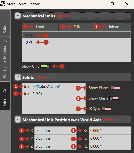
External mechanical units and joint configuration interface
What It Means
This interface segment is designed for setting up and managing mechanical units and joints within the robot system.
Mechanical Units
This section suggests that users can Load, Edit, or Unload mechanical units, such as end effectors or additional axis units. "(E1)" and "(E2)," represent individual external axes that can be selected for configuration. The "Show Unit" toggle, would display the selected unit within the simulation or program.
Joints
Here, individual robot joints are listed for configuration. "Joint 0" is identified as static or an anchor point, which likely means it does not move. "Joint 1 (E1)" appears to be a dynamic joint that represents an extension or external axis. The options "Show Planes" and "Show Mesh" are toggles for visualizing joint-related elements within the software, and "IK Sync" is a toggle for enabling inverse kinematics synchronization for that joint.
Mechanical Unit Position w.r.t World Axis
This section allows for the precise positioning of the mechanical unit relative to the world coordinate system, with fields for both positional and rotational values set to zero, indicating a default or origin position.
Edit Mechanical Unit Window
What You See
This is a window titled 'Edit Mechanical Unit', which appears after selecting the 'Edit' option in the External Axis tab. The window is divided into several sections: 'Mechanical Unit Info', 'Mechanical Unit Position', 'Joint Info', and 'Joint Definition'. There are input fields for 'Manufacturer' and 'Model' under the 'Mechanical Unit Info' section. 'Mechanical Unit Position' has fields for X, Y, Z coordinates and rotational values Rx, Ry, Rz, all set to zero. 'Joint Info' includes fields for 'Number' and 'Name', with 'Joint 0 (Static/Anchor)' filled in. The 'Joint Definition' section has a dropdown menu for 'Type', currently set to 'Rigid', and buttons for 'Mesh' and 'Axis Plane' labeled 'Select', 'Bake', and 'Clear'. On the right, you see a list with 'Joint 0 (Static/Anchor)' and 'Joint 1', with '+' and '-' buttons for adding or removing joints, and a 'C' button, for clearing.
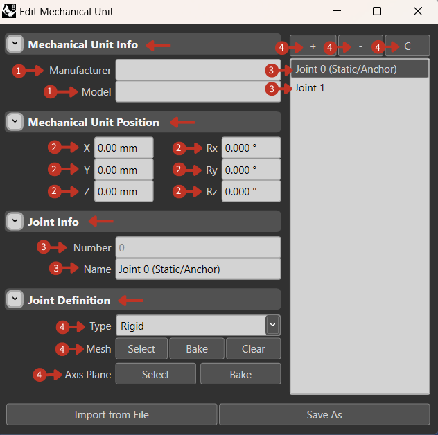
Detailed mechanical unit configuration and joint management interface
What It Means
This window is used for adding detailed information and settings for external mechanical units that you might attach to the main robot.
-
"Mechanical Unit Info": This dropdown menu is for documenting specific details of the mechanical unit, such as its manufacturer and model, which are essential for tracking and maintenance purposes.
-
"Mechanical Unit Position": Here, users can precisely position the mechanical unit within the robot's operating space using the X, Y, Z coordinates and Rx, Ry, Rz orientation inputs.
-
'Joint Info' is for specifying details about the mechanical unit's joints, which are pivotal points of movement or attachment. 'Joint 0' is labeled as 'Static/Anchor', indicating it's a fixed point, while 'Joint 1' represents a movable connection.
-
The 'Joint Definition' section is for defining the physical properties of the joint; selecting 'Rigid' suggests it does not allow for flexibility. The 'Mesh' and 'Axis Plane' functions are for visualizing and setting up the geometry and movement planes of the joints within the simulation and apply permanent settings through the "Bake" option. The buttons on the right are for managing the list of joints, allowing you to add new ones, remove existing ones, or clear joints, enhancing the mechanical unit's configuration for specific operational needs.