Line Scanner Coordinate System Configuration
What You See
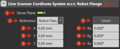
The Line Scanner Coordinate System w.r.t. Robot Flange interface features a Show Plane toggle, Reference dropdown menu, input fields for position (X, Y, Z) and orientation (Rx, Ry, Rz), and an Unset button.
Line Scanner coordinate system configuration relative to Robot Flange
What It Means
This panel is designed for aligning a line scanner's coordinate system with the Robot's Flange (the interface where tools are mounted on the robot).
Show Plane
The green toggle indicates that the plane of the line scanner is currently visible in the software. This visual aid helps users to see the plane which they are configuring in relation to the robot flange.
Reference
The dropdown menu allows users to select the reference point or system they are using for alignment. The option "Robot Flange" visible in the dropdown suggests that "Robot Flange" is the current reference, meaning the scanner's coordinates are being defined relative to this point.
Position Coordinates
"X, Y, Z": These fields determine the scanner's position in space, with all values at zero indicating that the scanner is positioned at the same point as the robot flange.
Orientation Angles
"Rx, Ry, Rz": These values set the scanner's orientation angles around each of the three axes. With all angles at 0.000°, the scanner is aligned with no rotation relative to the flange's orientation.
Unset
This button reverts the reference system to an undefined state, removing any current position and orientation settings.
Application Notes
- Line scanners are typically used for quality inspection
- Proper alignment is crucial for accurate measurements
- The Show Plane toggle helps visualize scanner coverage area