Tool Center Point (TCP) Position Interface
What You See
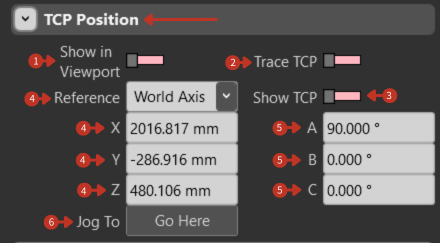
The interface, titled "TCP Position," displays toggle switches for "Show in Viewport" and "Trace TCP," a dropdown for "Reference" set to "World Axis," and numerical readouts for the X, Y, Z coordinates, and A, B, C orientation angles of the TCP. There are also buttons labeled "Jog To" and "Go Here."
Tool Center Point monitoring and navigation controls
What It Means
This section of the robotic control interface is crucial for the precise definition and monitoring of the TCP's position and orientation in relation to the robot's operational environment.
Visualization Controls
-
"Show in Viewport" Toggle: Activating this displays the TCP within the graphical simulation or workspace, aiding in visual alignment and adjustments.
-
"Trace TCP" Toggle: When toggled on, it allows the user to visualize the trajectory or path of the TCP during robot movement, which is beneficial for programming and diagnostic purposes.
-
"Show TCP" Toggle: This switch enables the user to show or hide the TCP within the simulation environment. It is a visualization aid that allows users to focus on or exclude the TCP from the display based on the needs of the task at hand.
Reference System
"Reference" Setting: The choice of "World Axis" suggests the TCP's coordinates are reported in relation to the overall workspace, providing a global perspective of the TCP's location.
Other reference options may include:
- Robot Base
- User Frame
- Tool Frame
Position Information
X, Y, Z Coordinates: Provide the exact spatial position of the TCP in millimeters
A, B, C Orientation: Show the angular position of the TCP in degrees, necessary for tasks requiring high precision, such as detailed assembly, machining, or inspection processes.
Navigation Controls
-
"Jog To" Button: Commands the robot to move to the specified TCP position and orientation using jogging motion (typically slower, controlled movement).
-
"Go Here" Button: Direct movement command to the displayed position (may use faster, programmed speeds).
Using TCP Position
For Programming
- Move robot to desired position
- Note TCP coordinates
- Use values in program code
- Verify with simulation
For Verification
- Compare actual vs. programmed positions
- Check for position drift
- Validate tool calibration
- Monitor during operation
For Troubleshooting
- Trace TCP to identify issues
- Compare with expected path
- Check reference frame alignment
- Verify coordinate transformations
Position Monitoring Tips
- Enable "Trace TCP" during path teaching
- Use "Show in Viewport" for visual confirmation
- Switch references to understand relationships
- Document critical positions
- Monitor for unexpected changes