Advanced Layup Parameters Configuration
What You See
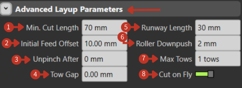
The Advanced Layup Parameters interface contains input fields for various parameters: Min. Cut Length, Initial Feed Offset, Unpinch After, Tow Gap, Runway Length, Roller Downpush, Max Tows, and a Cut on Fly toggle.
Advanced Layup Parameters configuration for composite processing
What It Means
This part of the interface provides detailed control over the parameters for a composite layup process, which is used to place materials like fibers or tows onto a mold or form.
Cutting Parameters
- "Min. Cut Length": Sets the minimum length for cutting the material, in this case, 70 mm. This ensures that the pieces laid are not shorter than the specified length.
Feed Control
-
"Initial Feed Offset": Adjusts the starting position of the material feed, set to 10.00 mm here, allowing for an offset before the layup begins.
-
"Unpinch After": Specifies a distance after which the material is released from a pinched or gripped state during layup, here set to 0 mm, indicating no unpinching is set.
Material Spacing
-
"Tow Gap": Determines the space between individual tows (strands of composite material), currently at 0.00 mm, implying no gap.
-
"Runway Length": The length of the area before the actual layup starts, set to 30 mm, allowing for material alignment and speed adjustments.
Compaction Control
- "Roller Downpush": This value, set at 2 mm, would control how much pressure the roller applies to the material, ensuring it's adequately compacted onto the surface.
Capacity Settings
- "Max Tows": Limits the number of tows that can be laid down simultaneously, with the interface allowing for 1 tow.
Operation Mode
- "Cut on Fly" Toggle: The engaged toggle indicates that the cutting of material can happen while the machine is in motion, enhancing efficiency by not stopping for each cut.
Default TCP Configuration
What You See
A section labeled "Default TCP" which includes a button for "TCP Plane" marked "Define," and a set of numerical input fields for the TCP's position (X, Y, Z) and orientation (Rx, Ry, Rz).
What It Means
This part of the interface allows users to establish a default setting for the Tool Center Point, which is a fixed point on the tool that is used as a reference for its movements and operations.
-
"TCP Plane" with a "Define" button: This allows the user to establish or define the reference plane for the TCP. Setting this plane is crucial for ensuring that the tool operates correctly in relation to the workpiece or other components of the robotic system.
-
"X, Y, Z" fields: These represent the spatial coordinates of the TCP relative to the robot's base or another reference point. In this case, X is set to 0.00 mm, indicating no offset along the X-axis; Y is set to -48.00 mm, suggesting an offset along the Y-axis; and Z is set to 411.50 mm, which would be the distance above the base or reference point.
-
"Rx, Ry, Rz" fields: These are the rotational coordinates of the TCP around each axis, expressed in degrees. Rx and Rz are set to 0.000°, indicating no rotation around these axes, while Ry is set to 180.000°, suggesting that the tool is inverted or flipped over the Y-axis.