Robot Configuration
Robot Name
What You See
A text box displaying the robot model name, showing KUKA KR 240 R2900 Ultra as an example.
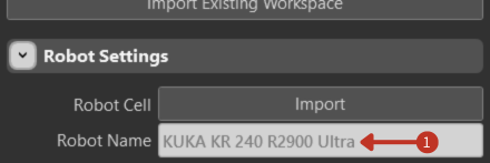
Robot Name field displaying the selected robot model
This displays the model of the robot you are working with. Each robot model has unique characteristics, capabilities, and operational parameters that affect planning and programming.
Load, More Options, and Clear Robot
What You See
Three control buttons: Load Robot, More Options, and Clear Robot.
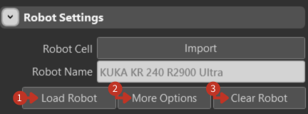
Robot management buttons for loading, configuring, and clearing robot configurations
Load Robot: Confirms the selection and loads the robot model into the workspace with all its specifications and capabilities.
More Options: Opens additional settings for advanced configuration, including custom parameters and specialized features.
Clear Robot: Removes the current robot from your workspace, effectively resetting the robot configuration.
Visibility Toggles
What You See
Toggle switches for controlling the display of various robot and workspace elements.
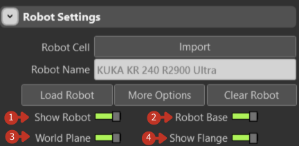
Visibility controls for customizing the 3D workspace display
Show Robot: Controls robot visibility in the simulation workspace. Hide the robot to focus on toolpaths or workpieces.
Robot Base: Toggles the robot mounting platform visibility. Useful for understanding spatial requirements and collision zones.
World Plane: Shows/hides the reference grid and coordinate system. Essential for spatial orientation and positioning.
Show Flange: Controls visibility of the robot's tool attachment point. Critical for tool alignment and TCP positioning.
Spatial Coordinates (X, Y, Z)
What You See
Input fields for spatial positioning with coordinate values in millimeters.
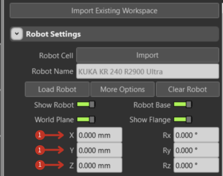
Spatial coordinate controls for robot base positioning
These fields define the robot's position in 3D space:
- X-axis: Left-right movement (lateral positioning)
- Y-axis: Forward-backward movement (depth positioning)
- Z-axis: Up-down movement (vertical positioning)
Coordinates are measured in millimeters from the world coordinate system origin.
Rotational Coordinates (Rx, Ry, Rz)
What You See
Input fields for rotational orientation with angle values in degrees.
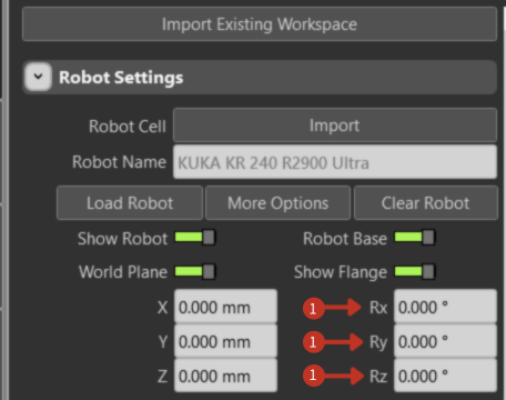
Rotational coordinate controls for robot base orientation
These settings control the robot's orientation in 3D space:
- Rx: Rotation around X-axis (pitch - nodding motion)
- Ry: Rotation around Y-axis (yaw - turning motion)
- Rz: Rotation around Z-axis (roll - tilting motion)
All rotations are measured in degrees from the base orientation.
Configuration Workflow
- Import or Select Robot: Start with Import Robot Cell or manually select your robot model
- Set Position: Define spatial coordinates (X, Y, Z) for robot base placement
- Set Orientation: Configure rotational coordinates (Rx, Ry, Rz) for proper alignment
- Load Robot: Click Load Robot to apply the configuration
- Verify Display: Use visibility toggles to confirm proper setup
- Save Configuration: Save the setup for future use