Zero Direction Interface
What You See
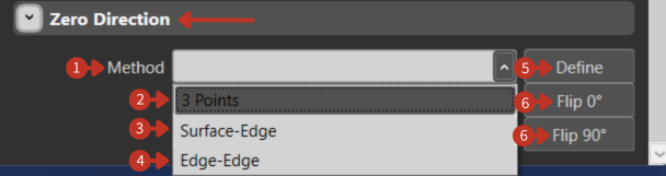
An interface titled "Zero Direction" which contains a dropdown menu for "Method" with options such as "3 Points," "Surface-Edge," and "Edge-Edge." Additionally, there are buttons for "Define," "Flip 0°," and "Flip 90°."
Reference direction definition for fiber orientation in composite structures
What It Means
This part of the software interface is designed for specifying the orientation of a zero or reference direction in relation to the geometry being worked on.
Method Selection
"Method" Dropdown Menu: Allows the user to choose the method for establishing the zero direction. The options available suggest different ways to define this orientation based on geometric features or points.
Available Methods
-
"3 Points": This option sets the zero direction based on three selected points within the geometry, defining a plane.
-
"Surface-Edge": Establishes the zero direction based on the alignment of a surface and an edge, which could be used to define a reference angle or plane.
-
"Edge-Edge": This is used to set the zero direction at the intersection or angle between two edges.
Control Buttons
-
"Define" Button: Finalizes the selection and orientation of the zero direction once the user has chosen a method and specified the necessary points or features.
-
"Flip 0°" Button: Reverses the zero direction by 180 degrees along the same axis.
-
"Flip 90°" Button: Rotates the zero direction by 90 degrees, changing the orientation perpendicularly.
Importance of Zero Direction
The zero direction is critical for:
- Defining fiber orientation angles
- Ensuring consistent ply alignment
- Coordinating multi-ply laminates
- Meeting design specifications
- Optimizing structural properties
Setup Guidelines
- Choose method based on geometry type
- Select clearly identifiable reference features
- Verify direction matches design intent
- Document zero direction for repeatability
- Test with single ply before full laminate