View/Edit Interface
What You See
Two interface snapshots displaying the details and options for a laminate configuration. The laminate, labeled as "Laminate 1," consists of 4 plies of composite material. The interface showcases each ply's material length, process time, and weight. Ply 1 also presents a contextual menu with options such as "Show Ply," "Suppress Ply," and others for detailed visualization and editing. Common actions like "Show Laminate," "Show Mold," "Show Layup Area," and "Flip Direction" are available for the entire laminate. There's an option to "Edit Laminate," which allows for modifications of the laminate configuration.
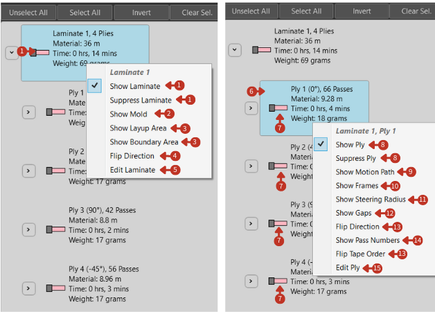
Laminate visualization and management controls with ply-specific options
What It Means
The interface is designed for a comprehensive approach to managing laminates in a fabrication or simulation setting.
Laminate-Level Controls
-
"Laminate 1" serves as the overarching element representing a complete set of plies. Options like "Show Laminate" and "Suppress Laminate" control the visibility of the entire laminate within the project, assisting with broad modifications or assessments.
-
"Show Mold" indicates whether the mold or form on which the laminate is placed is visible.
-
"Show Layup Area" and "Show Boundary Area" could toggle the visibility of the specific zones in which the laminate will be placed.
-
"Flip Direction" adjusts the orientation for all plies within the laminate.
-
"Edit Laminate" would launch a comprehensive editing mode for the entire laminate's configuration.
Ply-Level Information
For each ply, details such as:
- "Material": Total material length required
- "Time": Processing time for the ply
- "Weight": Material weight
These are essential for tracking resource usage, scheduling production, and understanding the physical characteristics of the laminate.
Ply-Specific Controls
The contextual menu for individual plies provides:
-
"Show Ply" and "Suppress Ply" control the display of the individual ply in the workspace.
-
"Show Motion Path" visualizes the path that the tool will follow to place the ply.
-
"Show Frames" could refer to displaying reference frames for the ply's orientation.
-
"Show Steering Radius" may visualize the curvature parameters applied during the ply's placement.
-
"Show Gaps" potentially illustrates the spacing between successive passes of the ply.
-
"Flip Direction" and "Flip Tape Order" allow adjustments to the ply's orientation and sequence.
-
"Show Pass Numbers" reveals the sequence of the ply's application within the laminate, providing clarity on the layup order.
-
"Edit Ply" opens settings for in-depth modification of the selected ply.
Usage Tips
For Visualization
- Use checkboxes to select multiple plies for batch operations
- Toggle visibility to isolate specific plies for review
- Show motion paths to verify toolpath planning
- Display gaps to check material placement
For Analysis
- Review material consumption per ply
- Check processing times for scheduling
- Verify weight distribution
- Analyze pass sequences
For Modification
- Suppress plies temporarily without deletion
- Flip directions to correct orientation issues
- Edit individual plies for fine-tuning
- Use bulk operations for efficiency