Robot Collision Detection Interface
What You See
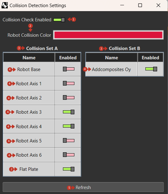
The interface, titled "Collision Detection Settings," features a master toggle labeled "Collision Check Enabled" and a color-coded bar for "Robot Collision Color." Below are two panels, "Collision Set A" and "Collision Set B," each listing elements like "Robot Base," robot axes, and an item named "Addcomposites Oy" with toggles to enable or disable collision checks for each. A "Refresh" button is situated at the bottom.
Collision detection configuration for robot and workspace elements
What It Means
This interface is dedicated to customizing and overseeing the collision detection parameters within a robotic simulation or operational setup.
Master Controls
-
"Collision Check Enabled" Toggle: This serves as a global switch to activate or deactivate collision detection for the robot's movements. When toggled on, it indicates that the system is actively monitoring for potential collisions.
-
"Robot Collision Color" Bar: Indicates the visual feedback color that will be used to highlight any detected collisions within the simulation environment, color can be customized according to the user.
Collision Sets
The two-set system allows for sophisticated collision checking:
Collision Set A
Typically includes:
- Robot components
- Primary tool elements
- Critical workspace items
Collision Set B
Typically includes:
- Secondary equipment
- Environmental objects
- Optional checking items
Element Configuration
"Collision Set A" and "Collision Set B" Panels: These sections allow for granular control over which components are included in the collision detection process.
Individual elements that can be toggled:
- Robot Base: The stationary base of the robot
- Robot Axes: Individual joint segments (A1-A6)
- Tool Components: "Addcomposites Oy" or other tools
- External Items: Fixtures, molds, obstacles
Element Toggles: Each toggle next to the component names enables or disables collision checks for that specific item. Green signifies that collision detection is active for that element.
Refresh Function
"Refresh" Button: Refreshes the collision detection settings to reflect any changes made or to reload the current state of the simulation or operational environment.
Collision Detection Strategy
Setup Best Practices
-
Essential Checks
- Always enable robot self-collision
- Include all fixtures and molds
- Check tool-to-part interactions
-
Performance Optimization
- Disable unnecessary checks
- Use simplified meshes where possible
- Group related components
-
Safety Margins
- Add clearance to collision meshes
- Account for tool deflection
- Consider material spring-back
Common Collision Scenarios
Self-Collision
- Wrist-to-arm contact
- Tool-to-robot interference
- Cable management issues
Environmental Collision
- Fixture interference
- Workspace boundary contact
- Overhead obstruction
Process Collision
- Tool-to-part contact
- Material handling interference
- Multi-robot coordination
Troubleshooting Collisions
When Collisions Detected
-
Identify Location
- Note frame number
- Check collision pairs
- Review robot configuration
-
Analyze Cause
- Path planning issue
- Clearance problem
- Configuration error
-
Implement Solution
- Adjust waypoints
- Modify approach angles
- Add intermediate positions
- Increase clearances
False Positives
Common causes:
- Overly conservative meshes
- Incorrect mesh alignment
- Outdated collision geometry
Solutions:
- Refine collision meshes
- Update tool definitions
- Verify coordinate systems
- Adjust detection sensitivity
Visual Feedback
Collision visualization helps identify issues:
- Color coding: Red for active collisions
- Transparency: See through to collision point
- Highlighting: Affected components emphasized
- Distance display: Near-miss warnings